IW3SGT LF-VLF loops |
|
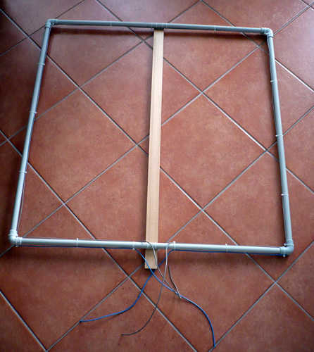
My first indoor loop
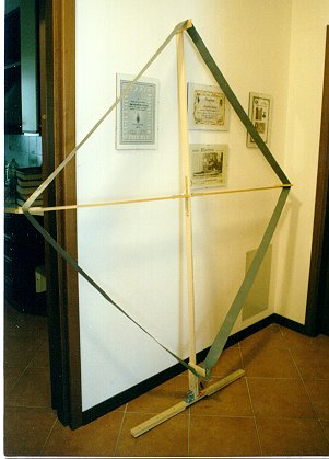
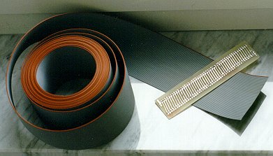
I have used a 50 wire bus computer cable,
tuned with four BB112 varicap and followed with
a PRE (FET+BJT). The side lenght was 1,25mt. The loop had around 10 mH and 53 ohm c.c. resistance and it tuned from 56kHz to the end of LF. It was my first loop for my first 137kHz LF reception experience :-)
This picture was publied in "Radiokit" radio and electronics monthly magazine on 137kHz article by IK1ODO.
The loop was hidden behind a furniture in the living room ... wife was tolerant until new furnutire and after ... ciao ciao maxiloop :-( |
|
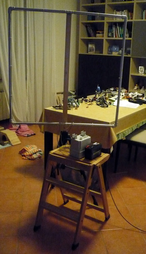
Portable loop
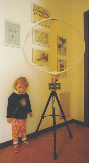
For this loop I have two targets: portability and VLF capability. I used 1 mt diameter "hula-hop" with 23 turn of 1,5 mmsq wire. The shield is aluminium foil interrupted for 2-3 cm.
The loop has a 1,26
mH and 1,6 ohm c.c. resistance. With four BB112
varicap it tunes from 123 kHz to high part of
LF.
|
|
. |
Modular loop
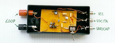
Variable capacitors are not simple to find and sometime expensive, my idea is simple: one "base" with variable capacitor (and some fixed switched) and a frame interchangeable inside. The base have a capacity range from ~50pf-8.3nF. The air variable capacitor have a range of 40-920pf and there are 4 switch with 0.5, 1, 2 and 4nF. The first frame have 0.5m side length, 13 bifilar turns with black and red loudspeaker cable. The frequency range is 125-820kHz with 13 bifilar turns, and 67-283kHz with serie windings (26 turn). A HI-Z PRE can be added on the main winding but too much signal causes too noise and bad performance on RX. I prefer single turn connection, less signal but the tuning is very sharp. For this loop I use a PRE as the famous MINIWIP antenna (bettery powered). Base inside view |
Base and cap controls |
Bifilar winding (13 turns) and ... |
The base can be use with other windings. In this picture I use a ferrite rod (~19.5mH and 125kHz frequency resonance). This system has a frequency range between 12-112kHz :-) |
... serie connection (as 26 turns) |
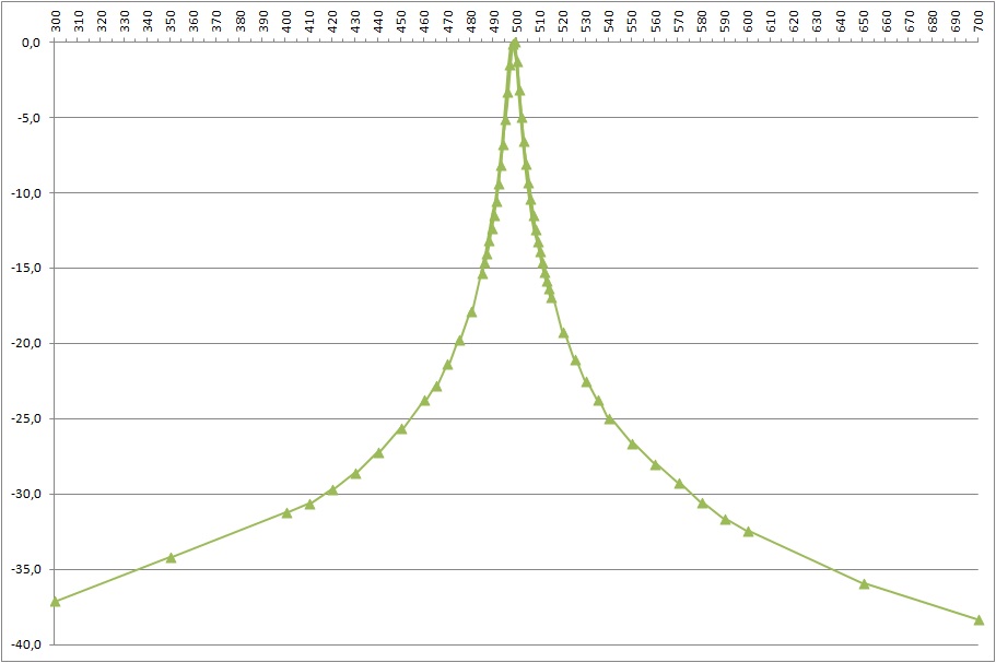
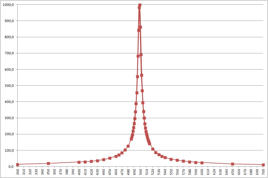
Some measurements about the 50x50cm square loop: Q = 100 at 500kHz, Q = 86 at 137kHz and Q = 55 at 137kHz with serie connection. 500kHz selectivity graph (V) 500kHz selectivity graph (dB) |
|
Work in progress With this loop I would improve the performance on LF. I used again PVC pipes and a wood rod. The winding have 13 turn of 1.5mm wire (cable for mains) and the link have 1 turn outside the pipe.The square is 0.9m side. A LCR bridge report 535uH and a Q=49 at 10kHz. First impressions is a good improvement of signals in the range 270-350kHz ()NDB). I see the loop resonance in the 400-450kHz range probably caused by the high wiring capacitance. |
È vietata qualsiasi
utilizzazione, totale o parziale, dei contenuti
inseriti nel presente sito, ivi inclusa la
memorizzazione, riproduzione, rielaborazione,
diffusione o distribuzione dei contenuti stessi
mediante qualunque piattaforma tecnologica,
supporto o rete telematica, senza previa
autorizzazione scritta di Alessandro Kosoveu
IW3SGT (e-mail: iw3sgt_@_libero.it remove _). Any use , total or partial , of the content posted on this site, including the storage, reproduction, editing, distribution or dissemination of the contents by means of any technology platform, support, or computer network are forbidden without the written permission of Alessandro Kosoveu IW3SGT (e-mail: iw3sgt_@_libero.it remove _). |